Balcony Solar Mounting & Wind Safety (2026)
A structure-first method for railing mounts, wall brackets and floor stands—without universal wind-speed or ballast guesses.

WattRank is reader-supported: we may earn a commission if you buy through links in this guide. This never affects our rankings.
Key facts
- Wind acts on panel area and geometry; module weight alone cannot establish mounting safety.
- A mount rating does not prove that the railing, parapet, wall or its connection to the building can carry the transferred loads.
- Changing module dimensions, tilt, fasteners or attachment points can invalidate a tested or engineered mounting configuration.
- A secondary restraint is a backup only when the manufacturer or a qualified design specifies its material, anchor and routing.
- Fastener torque should come from the exact manual, and critical connections should be checked at commissioning and after severe weather.
What makes a balcony solar mount safe?
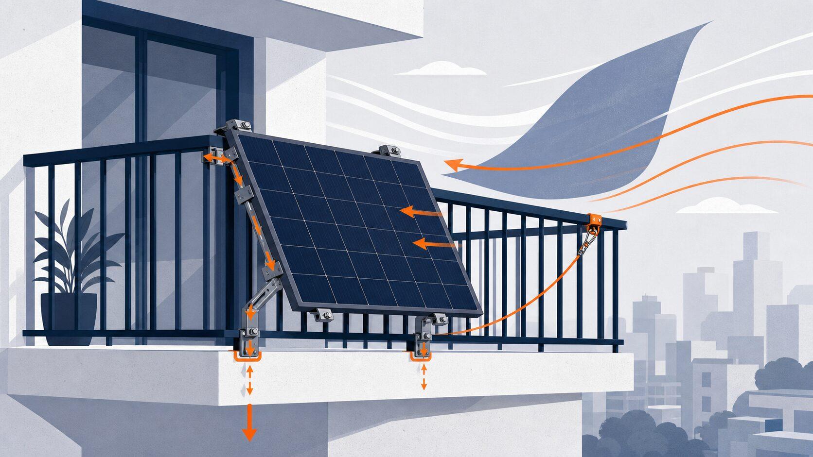
Safety exists only when every link between the module and the building is known. Wind pressure reaches the module face, passes through its frame into rails or brackets, then through bolts, clamps or anchors into a railing, wall, parapet or floor. That support finally transfers the action into the building. A strong bracket attached to weak, corroded or unsuitable structure is still a weak system.
Treat mounting as a mechanical project separate from the electrical connection. This guide covers panels used in grid-tied plug-in solar, but the same falling-object risk exists for a panel charging a portable solar generator. Passing the mount gate does not prove that a grid-tied system may connect at the location, and electrical permission does not approve an exterior attachment.
| Link in the load path | Evidence to collect | Typical stop signal |
|---|---|---|
| Module | Exact model, dimensions, mass, frame and permitted clamp zones | The mount names different dimensions or forbids that orientation |
| Mount | Compatible module list, layout, exposure limits and complete manual | Marketplace hardware has no traceable design data |
| Fasteners | Specified grade, size, washers, locking method and torque | Substituted bolts or no torque instruction |
| Supporting element | Material, condition, dimensions and permitted attachment method | Loose, corroded, cracked, thin, glass or otherwise unverified support |
| Building connection | Evidence that the support and its anchors accept the added actions | The railing or parapet capacity is unknown |
| People and property | Safe installation access, exclusion zone and consent | Work requires leaning outside or exposes a public area below |
Why panel weight is the wrong shortcut
Static weight pulls mainly downward. Wind can push inward, pull outward, create uplift and reverse direction as gusts wrap around a façade. The resulting force also creates a turning effect because the panel face sits away from the support. A hand test in calm weather says almost nothing about those combinations.
Wind pressure grows roughly with the square of wind speed before site and shape factors are applied: doubling speed corresponds to about four times the basic dynamic pressure, not twice. That relationship explains why a generic “supports 30 kg” payload number cannot substitute for wind design. It is not a DIY calculation method; real design also depends on height, terrain, corner effects, shielding, panel area, tilt, gaps, pressure coefficients and local code.
| Input | Why it changes the answer | What not to assume |
|---|---|---|
| Panel width and height | Set the area exposed to pressure | Two equal-watt modules have equal dimensions |
| Tilt and projection | Change pressure, uplift and leverage | More tilt is only an energy decision |
| Building height and edge position | Can increase exposure and local façade effects | A ground-level rating automatically applies upstairs |
| Terrain and shielding | Open coast, valley, courtyard and dense city differ | A nearby wall always protects the panel |
| Attachment spacing | Controls force and moment at each connection | Extra random clamps repair an undocumented layout |
| Design wind basis | Connects the product configuration to a location | A Beaufort label or maximum speed from another product is transferable |
Choose the mounting family before the hardware
The correct family follows the structure you are actually allowed to load. Railing mounts can be removable, but they rely on both the rail and its building anchors. Wall mounts can provide a direct structural route, but require the right substrate, anchors and permission. Floor stands avoid loading a railing yet need a verified ballast or anchorage design and enough space to keep exits and drainage clear.
| Mounting family | Can fit | Evidence required | Common trap |
|---|---|---|---|
| Railing clamp or hook | A named metal rail geometry in sound condition | Rail dimensions/material, full restraint layout, module compatibility, exposure limit | Clamping glass, decorative infill or a top rail without structural evidence |
| Wall or parapet bracket | A verified structural substrate and suitable anchors | Substrate survey, anchor specification, edge distances, waterproofing and consent | Choosing an anchor from wall appearance alone |
| Ballasted floor stand | A level load-bearing floor with drainage and clearance | Site-specific ballast/layout table or engineering, anti-slip and membrane protection | Adding household objects as improvised ballast |
| Mechanically anchored floor stand | A structure approved for penetrations | Anchor design, waterproofing detail and building approval | Drilling before locating structure or services |
| Lightweight/flexible module restraint | Only the surfaces and fixing pattern named by its manual | Every required fixing, UV/weather durability and edge restraint | Assuming low mass means low wind force |
Do not use a photovoltaic module as a replacement guardrail. Germany’s building-technology authority, DIBt, distinguishes a removable plug-in PV module from one that performs a building function such as fall protection; it also states that the building parts used for mounting must be suitable for loads including wind. Keep the original guardrail function intact and evaluate the solar attachment as an added load.
Audit the railing, wall or floor as carefully as the bracket
Record the support material and geometry before shopping. For a railing, note whether the proposed clamp bears on a round or square metal member, a concrete parapet, timber, glass or composite infill. Check corrosion, loose posts, cracks, previous repairs and movement at the connection to the slab or wall. A clamp must not crush a thin tube, damage a protective coating or load a decorative piece as if it were structural.
Glass balustrades are a specialist case. Do not clamp to glass or route a restraint around it unless the complete method is explicitly designed and approved for that system. A wall also needs more than the label “masonry”: brick, hollow block, concrete, insulation systems and façades require different anchors and edge distances. Floor stands need verified floor capacity as well as wind restraint; ballast is another permanent load, not a free safety margin.
- Ask the landlord, condominium, homeowners association or building manager for written exterior-work consent and any available structural information.
- Photograph the full support, its connections to the building and every proposed attachment point before covering them.
- Compare measured dimensions with the mount manual; do not make a near-fit work by bending hooks, packing random shims or drilling new holes.
- Escalate to a structural professional when support capacity, anchor substrate, wind exposure or a high-consequence drop cannot be established from approved documentation.
Match the exact module, mount and fastener set
Compatibility is configuration-specific. Confirm the exact module length, width, thickness, mass, frame shape and mounting-hole or clamp-zone requirements. Then check the permitted portrait or landscape orientation, tilt range, rail spacing, number and position of supports, and whether the inverter or cable routing adds loads the mount was not designed to carry.
Use the supplied or explicitly specified fastener grade, diameter, length, washers, nuts and locking parts. Torque is part of the design: too little can allow slip and vibration; too much can strip threads, crush a rail or damage the module frame. US Department of Energy severe-weather guidance identifies fastened joints as a recurring wind-loss factor and recommends proper installation plus torque auditing. Use the exact manual value, not a generic torque table.
| Change | Why it matters | Safe response |
|---|---|---|
| Larger or differently framed module | Changes area, leverage and connection geometry | Obtain documented compatibility or a new design |
| Greater tilt | Changes wind actions and bracket forces | Use only a listed angle for the site/configuration |
| Fewer clamps or alternate holes | Redistributes force and may load weak frame zones | Restore the specified layout |
| Different bolts or washers | Changes strength, bearing, corrosion and locking behavior | Use the named specification |
| Added microinverter on the panel frame | Adds mass, heat and cable loads | Follow both mount and inverter placement instructions |
| Mixed-metal contact outdoors | Can accelerate corrosion in wet conditions | Use the documented material isolation and hardware |
What should a secondary safety restraint do?
A secondary restraint is meant to limit the consequence of a primary attachment failure; it does not raise the rated wind capacity of the main mount. It must be independent enough that one loose clamp or failed member does not defeat both systems, and it needs a verified anchor that is not a decorative rail segment or the same weak fastener.
Use a restraint only when the manufacturer or a qualified design specifies compatible material, strength, termination, routing and slack. It must not cut into cables, rub sharp edges, create corrosion, load glass or become a trip hazard. A cable tie, rope, luggage strap or improvised wire has unknown ageing and connection strength and is not a substitute for a designed fall-arrest detail.
Install the panel without creating a fall hazard
Plan the lift before opening the hardware. Assemble as much as possible at floor level, keep tools and loose components inside the balcony, and establish an exclusion zone below wherever people or property could be struck. Official manufacturer instructions commonly call for two people and protective equipment; OSHA likewise warns that solar panels should not be carried while climbing ladders.
Do not lean over a guardrail while holding a module, stand on furniture, work from an unsecured ladder or remove part of the existing fall protection to gain access. HSE’s work-at-height hierarchy is useful even for a household task: avoid the exposure where possible, prevent falls with a safe workplace or suitable equipment, and use competent help where the risk cannot be controlled. Postpone work in rain, ice or gusting wind.
| Installation phase | Control | Check before continuing |
|---|---|---|
| Preparation | Cover or electrically isolate the module as its manual requires; inventory parts | Exact hardware and instructions are present |
| Ground-level assembly | Build the permitted frame orientation without modifying parts | All members face the correct direction |
| Access and lift | Use enough people and suitable lifting/access equipment | Nobody must overreach or stand below |
| Primary attachment | Install every clamp/anchor in the stated sequence | Support is seated without damage or distortion |
| Torque and locking | Use a calibrated tool where the manual gives torque | Witness marks or a record show completion |
| Secondary retention | Fit only the specified independent restraint | Anchor, routing and slack match the design |
| Cable management | Support UV-rated cable without pinch, abrasion or water entry | No cable carries mechanical panel load |
Commission and inspect the mount as a system
Commissioning is a documented inspection, not a shake test. Compare the finished installation with the manual, record torque completion, photograph critical connections and confirm the panel cannot contact doors, glazing, drains or escape routes through its permitted movement. Check that the module frame is not twisted and the rail or wall shows no new deformation.
Follow the product’s maintenance interval. Also inspect after severe wind, impact, building work or any observed movement. Look for loose or missing hardware, shifted witness marks, corrosion, cracked coatings, elongated holes, frayed restraint, damaged module glass or frame, chafed cables and movement where the support joins the building. If anything has changed, isolate the system as instructed and secure the area; do not continue operating because electrical output appears normal.
| Trigger | Inspection focus | Escalate when |
|---|---|---|
| Initial commissioning | Complete configuration, torque, locking, restraint and cable clearances | Any instruction cannot be satisfied |
| Routine interval | Movement, corrosion, wear, UV damage and drainage | A connection will not hold specified torque |
| After strong wind or impact | Module/frame damage and every load-path connection | The panel shifted, hardware loosened or support moved |
| After building maintenance | Unapproved removal, substitution or disturbed anchors | The original configuration is no longer intact |
| Before relocation | Whether hardware is reusable under the manual | Parts are deformed, corroded or single-use |
Should you remove panels before a storm?
There is no universal yes. A system designed and documented to remain installed for the site’s conditions should follow its severe-weather instructions. A removable product may specify a stow angle, shutdown or pre-storm removal threshold. Follow that exact procedure early, while conditions are safe; never climb, lean outside or dismantle a panel once strong winds have arrived.
If the manual provides no applicable wind basis, the location exceeds it, or the support was never verified, the safe conclusion is not to improvise a storm threshold. Keep the area below clear, contact the manufacturer or a qualified professional, and correct the design in safe conditions. A weather app cannot repair an undocumented attachment.
The five-gate mounting decision
| Gate | Pass | Pause or reject |
|---|---|---|
| Property | Written permission and required building/planning route are clear | Exterior attachment is not approved |
| Structure | Support and building connection can accept the added configuration loads | Capacity or condition is unknown |
| Configuration | Exact module, mount, angle, hardware and site exposure are documented | Any part relies on substitution or a generic claim |
| Installation | Work can be completed without uncontrolled falls or falling objects | It requires overreaching, unsafe access or work in wind |
| Lifecycle | Inspection, severe-weather and removal instructions are available | No one can state how the mount will be checked or retired |
Passing all five gates supports a mounting decision; it still does not establish electrical eligibility. Check the current grid-connection pathway, complete-system evidence, circuit and meter requirements separately. Where no specific plug-in framework exists, describe the result as local research required rather than assuming the system is prohibited.
Sources and next steps
This method uses DIBt’s balcony-PV building guidance, US Department of Energy and FEMA severe-weather evidence, official work-at-height guidance and manufacturer instructions. Roof and utility-scale research does not create a balcony rating; it identifies failure modes and evidence that a balcony-specific configuration must address.
- DIBt — Building requirements for PV modules and plug-in balcony systems
- US Department of Energy — Severe Weather Resilience in Solar Photovoltaic System Design
- FEMA — Guidelines for Wind Vulnerability Assessments of Existing Critical Facilities
- HSE — Introduction to working at height safely
- OSHA — Solar energy fall hazards
- EcoFlow — Adjustable Ground & Suspended Solar Bracket installation guide
Frequently asked questions
How much wind can a balcony solar panel withstand?
Only the rating or design for the exact module, mount, layout and site can answer that. A maximum speed from another bracket is not transferable, and a payload rating covers weight rather than the complete wind action. Verify the product’s design basis, height or exposure limits and supporting structure; otherwise obtain a qualified site-specific assessment.
Can I attach a solar panel to any metal balcony railing?
No. The clamp must match the rail’s material, shape and dimensions, and the railing plus its building anchors must accept the added wind and gravity loads. Thin, corroded, loose or decorative members can be unsuitable. Do not drill or clamp until the structural load path and property permission are documented.
Are glass balcony railings suitable for solar panel clamps?
Do not clamp to glass unless a complete, approved system is specifically designed for that balustrade. Glass, its fixings and its fall-protection role make improvised loading high consequence. Use an independently supported floor or wall solution only when the structure, permissions and wind design are verified, or consult the building designer.
How much ballast does a balcony solar floor stand need?
There is no safe universal weight. Required ballast depends on the tested stand, module dimensions, tilt, friction or attachment method, building height, edge position, wind climate and substrate. Use the manufacturer’s applicable layout table or an engineered calculation, and verify that the balcony floor can carry the added permanent load.
Should balcony solar panels have a safety cable?
Use a secondary restraint when the manufacturer or a qualified design specifies one. It should have a defined material, termination, routing and independent verified anchor. It limits the consequence of primary-mount failure; it does not increase the main mount’s wind rating. Rope, luggage straps, cable ties and improvised wire are not equivalent.
How often should balcony solar mounts be inspected?
Follow the exact manufacturer interval and check the system at commissioning, after severe wind or impact, after nearby building work and whenever movement is noticed. Inspect the module frame, brackets, torque or witness marks, locking parts, corrosion, restraint, support anchors and cable wear. Isolate and secure the area if any load-path component has shifted or deteriorated.
Check your location
Framework status and exact product eligibility are separate checks.